In the Incubator layer of the design stack, processing units can be arbitrary programs. In the next layer, the Cytoplasm layer, processing units are called 'proteins' and they are not arbitrary programs. Rather, they are created out of smaller building blocks, called abstract domains, or just domains, for short. These building blocks are connected to one another in precise ways to form proteins.
Domains come in different flavors. Each different flavor of domain has a specific use. No single flavor of domain does much on its own. Their power comes through the combinations that they can appear in. Here is a list of the different domain flavors, along with a word about their use.
Domains may be connected to one another to form more useful entities. They are connected through interfaces. Each domain may have many interfaces. Interfaces are characterized by three properties: a direction, a type and a name. The interface's direction is either acceptor or expressor. The direction of an interface usually refers to the flow of information along the interface, but it does not need to. As we will see later, interfaces must be joined in pairs, an acceptor to an expressor. This is the main property of the interface direction.
The type of an interface determines what kind of values may be transmitted along the interface. For instance, there are boolean interfaces and string interfaces. Interface joining is typechecked so that only interfaces of the same type may be joined.
The name of an interface identifies what the interface is used for. For example, an interface may have two boolean acceptor interfaces, one for triggering the function of the domain and one for repressing it entirely. Conceivably, these interfaces would have names like “trigger” and “repress”. Certain interfaces may also be arrays of variable length. In this case, the name of the interface followed by an integer index refers to an element of that array.
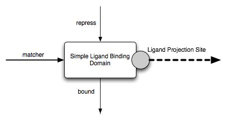
Consider the Simple Ligand Binding Domain. It has three interfaces:

Projection sites interact with the Cytoplasm through well-defined operations, called operations. There are input operations and output operations. Both ligand projection sites and structural projection sites have their own private sets of both input and output operations. They correspond exactly to those operations that can be performed by the underlying Incubator. We now list all the possible operations.
A ligand projection site must accept the following input operations:
A structural projection site must accept the following input operations:
What do all these interfaces and projection sites and operations actually do? They participate in the dynamic nature of domains. Domains transform input values and input operations into output values and output operations through a process we call conformation change in analogy with the physico-chemical transformations of proteins. Conformation changes are a gradual adaptation of the values on the output interface and the output operations issued by the projection sites in response to the input values and input operations. The graduality is important, as domains do not react instantaneously. In fact, in order to most flexibly define the domains, the reaction times are left unspecified.
We formalize these issues presently. We divide the description of a domain response in two separate entities: the functional logic of the domain, which prescribes the domain dynamics from a purely functional point of view; and the conformation engine, which supplements the functional logic with time dependent evolution functions.
The domain functional logic specification is a quadruplet (D, M, I, O) where
The domain operation IO specification associates to each state s in S in the state machine a mapping h^o_s from the domain input operations O_i to the machine transitions T. In other words, the domain operation IO specification describes how the domain responds to input operations. Note that the response is always in terms of state machine changes. This restriction simplifies the model. It requires that a domain with a projection site that acts in a non-trivial way have more than a single state.
This completes the description of the functional logic of a domain. We give a number of examples below — it's really much simpler than it looks!
The second part needed to fully describe domain conformation changes is the conformation engine. It adds to the functional logic of a domain a time dependent evolution function. FIXME: What's the best way to describe the conformation engine? Define in terms of a pair of a partial behavior function and a partial state history, so we can connect with those definitions for a domain assembly later on. In the end, it's not important, and it's not used. What's important is to show that the changes in output values and the emission of output operations takes some time. This time is bounded by an amount which may be specified. Otherwise, it is left flexible, up to the implementation of the domains proper.
Abstract domains are inherently attached with their functional logic but they do not have, by definition, a conformation engine. An abstract domain with a compatible conformation engine is a concrete domain. Both the functional logic and the conformation engine are needed to fully describe how proteins made up of many domains will behave. As we will see below, the functional logic alone will leave the behavior of a domain assembly ambiguous and adding gluing the conformation engines together will resolve the ambiguities. However, introducing an equivalence relation on the possible behaviors will eliminate the need to know the details of the conformation engine. This simplification will prove very useful.
The framework for specifying domain conformation changes has been given. After a few short notes we present the functional logics for all the Monod domains in the subsections below.
The behavior of domains with respect to certain input values can have certain stereotypical values. Certain input interfaces are optional. This feature comes into play when the acceptor interface is not connected to an expressor interface — when it is naked, as we introduced earlier. In this case, a default value is clamped to the interface.
It is sometimes the case that the interface can not be left naked. This restriction must be specified as part of the domain specification. In this case, a default value does not need to be specified.
Finally, it is interesting to contrast the conformation changes in the simulated Monod world with those in the biological world. Biological proteins manifest all sorts of behavior, including allostery, which is the ability to exist in different states and even integrate different sources of logical input to compute a compound logical state; the ability to cleave ligands and join different strands; the ability to slide along a ligand. The Monod simulations also offer these abilities. A contrast between the real biological world and the simulated model is that physico-chemical conformation changes certainly qualify as complex quantum phenomena, while the Monod model has no pretense at incorporating such aspects. While this is certainly a notable difference, its computational significance is less clear. To the best of the author's knowledge, there are no clear examples of essential quantum protein function. Of course, our knowledge of protein interactions is still fairly basic so the situation is liable to change.
The SLBD is used to provide a simple indication that a ligand is bound. Binding can be repressed. No alteration can be made to the ligand. Hence, this domain is mostly useful as a regulatory domain.
The SLBD interfaces and projection sites have already been described earlier and an image presented. The matcher acceptor interface is mandatory. The functional logic of the domain is independent of the value of this interface. Hence, there is no need to refer to it further in the discussion below. The repress acceptor interface is optional and its default value is false. Hence, for all practical purposes, the input space is a simple boolean, corresponding to the repress interface, and the output space is also a simple boolean, corresponding to the bound interface.
The functional logic is described, if cryptically, in the following diagram.
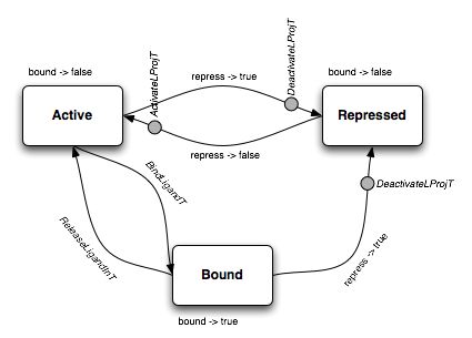
This diagram shows that the state machine M has three states, named Active, Bound and Repressed. The transitions between the states are also shows.
Consider first the Active state. In this state, the ligand projection site is active and participates in matching at the Incubator level. The h_i function of the domain interface IO specification is such that the (only) output value bound is false. To repress=false, the function does not associate a state transition; to repress=true, the function associates a transition to the Repressed state and the emission of a DeactivateLProjT output operation. The h_o function only reacts to the BindLigandT input operation, triggering a transition to the Bound state.
In both the Repressed and Bound states, the projection site does not participate in ligand matching in the Incubator. The domain IO specification is easily deducible from the figure.
The LBDR is used to bind to ligands and change them. Hence, this domain goes further than the SLBD. Ligand alteration is not arbitrary, however. Instead, two ligands must be bound and fragments may be exchanged between them. Ligand alteraction is thus conservative, in the sense that no ligand chunks may be created or destroyed by the LBDR. Other domains handle this task.
The exchanges are performed through permutations, as follows. First, the LBDR is configured with an array of matchers [m_1, m_2, ..., m_k] and with two permutation states S_1 = (P_1^1, P_2^1) and S_2 = (P_1^2, P_2^2), each of which identifies an ordered partition of the matchers into two lists. Each P_i^j is a list of indices from the set of matchers [0, 1, ..., k] and defines a compound matcher, which is a matcher which will match the concatenation of the corresponding matchers. The permutation states must be exhaustive, that is, for S_1, P_1^1 cup P_2^1 = [0, 1, ..., k] and similarly for S_2. Finally, the behavior of the end-points of the permutation states must be indicated. There are two possibilities: either the ligands are cleaved the tail end of the second one is affixed to the start of the first and vice-versa, or only the matching regions are rearranged.
An example of the permutation states is shown in the figure below.
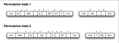
In this example, there are twelve matchers. The first permutation state lists them in the same order they are defined, though this does not need to be the case. The second permutation state lists the same matchers in a different permutation. The <<1-type tags indicate that there is no rearrangement of the extended ligands: only the matching regions are changed. This domain takes a ligand of the form “is this a [N]bird?” and transforms it into “this is not a bird”. The “[N]” appears as a form of tag. The second projection site serves as a simple holder.
The LBDR clearly has two ligand projection sites. It is defined by the following interfaces:
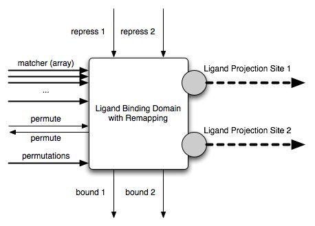
The matchers in the matcher array are indexed 0, 1, ..., k as described earlier. The permutations string acceptor must follow a simple pre-defined format. If it does not, the domain is invalid and will be rejected. The format simply lists the matcher indices, separated by colons, with both compound matchers separated by “|” and both permutation states separated by “||”. For instance, the example shown in the figure above would read as follows (the string is broken with a \ to make it fit):
     <<1:1:2:3:4:5:6:7:8:9:1>>|<<2:10:11:12:2>>||<<1:3:2:1 \
     :4:10:12:5:6:8:11:1:1>>|<<2:9:7:2>>
The repress1, repress2, bound1 and bound2 interfaces play the same role as the corresponding interfaces in the SLBD, but for the two projection sites of the LBDR. The permute acceptor interface flips the projection sites from the first permutation state (when permute = false) to the second permutation state (when permute = true). The default value of permute is false. The functional logic of the LBDR is shown in the figure below.
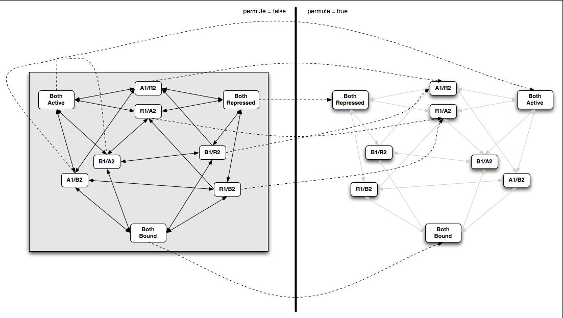
The permute expressor is set to the value of the permute acceptor after the flip is executed. This feature is needed in order to create a well-defined protein behavior, as we will show when we assemble multiple domains into domain assemblies. FIXME: Explain the functional logic further. Note how when a single one of the two projection sites is bound and the permutation state is flipped, the ligand is released.
FIXME: Rewrite this section. This is just a brain dump.
The LID is used to compute a logical function of its boolean inputs and presents the result on its sole boolean output. It has the following interface:
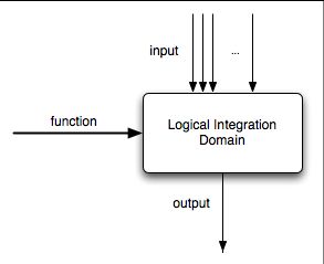
The function must be a string which defines a valid boolean function on the inputs i[0], i[1], ..., i[k], where k is the index of the last matcher in the input array. The function definition can use the &, | and ! operators. The domain does not have any projection site and hence no input or output transition. The domain state machine has a single state. The output value is equal to the result of applying the function to the input.
FIXME: Example
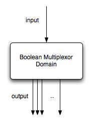
The BMD has a single state, a single boolean acceptor interface and a single boolean expressor interface array. It outputs the value of the input on all the members of the output array. This domain is useful because interfaces can only be connected one-to-one. FIXME: Expand.
